Data link layer protocol simulator working guide
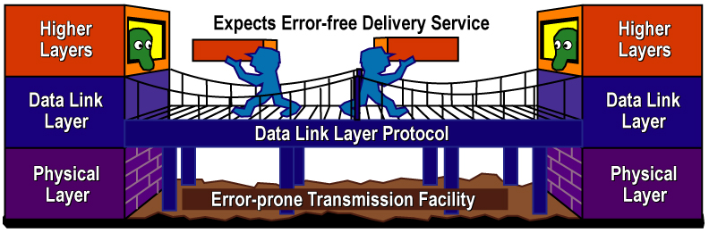
This manual describes how the simulation program operates for a data link layer protocol. This is an implementation of connection oriented protocols namely Go Back N and Selective Repeat protocols using the java language. The protocols shows the frames been transmitted via the transmitter channel from the transmitter (User 1/ client) to the receiver (user 2 /server). This is demonstrated when the simulator is started. Performance of the protocols is based on the time used for transmission and the efficiency is calculated mathematically based on the average number of frames per window length transmitted through the transmission channel.
Also informative message which describe the actions of the protocols known as events are explained in different operations scenario such as when a frame is killed or lost and how it is resent for both protocols. The simulator provides a visual representation of these frames and the events are recorded in a text window.
2. Simulation mechanism of the protocols
The protocols namely go back N and Selective repeat /Retransmission is written in java which is in the package DLLPS. The protocols were designed based on the details learnt in the in textbook (Computer Networks, Chapter 3, Andrew Tanenbaum).The class DLLPS provides a platform for operations such as to send frames that is initiated with the “Start simulation” button. Figure 1 shows the simulation window of the applet when it is run from eclipse before it starts any transmission. The start button is basically what begins the transmission of frames through the transmission channel. The color codes assist the user to know current state of the frames. What each color codes denotes is in the legend. The two protocols have different methods that are appropriately called when any events occur. This is reflected on the simulation window.
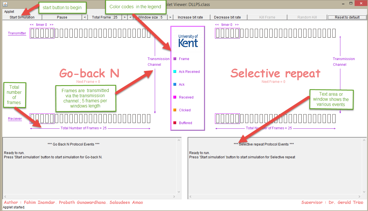
Figure 1 - Simulation window
As a continuation from figure 2a, in figure 2b the last bit arrives for the frames 0 to 4. The frames are checked if it is in order , if everything is okay, an acknowledgement for each of the frames is generated and sent to the transmitter confirmation that the transmission was successful .Then the next sequence of frames(frames 5-9) to be sent are initiated. All this information is noted in the events window.
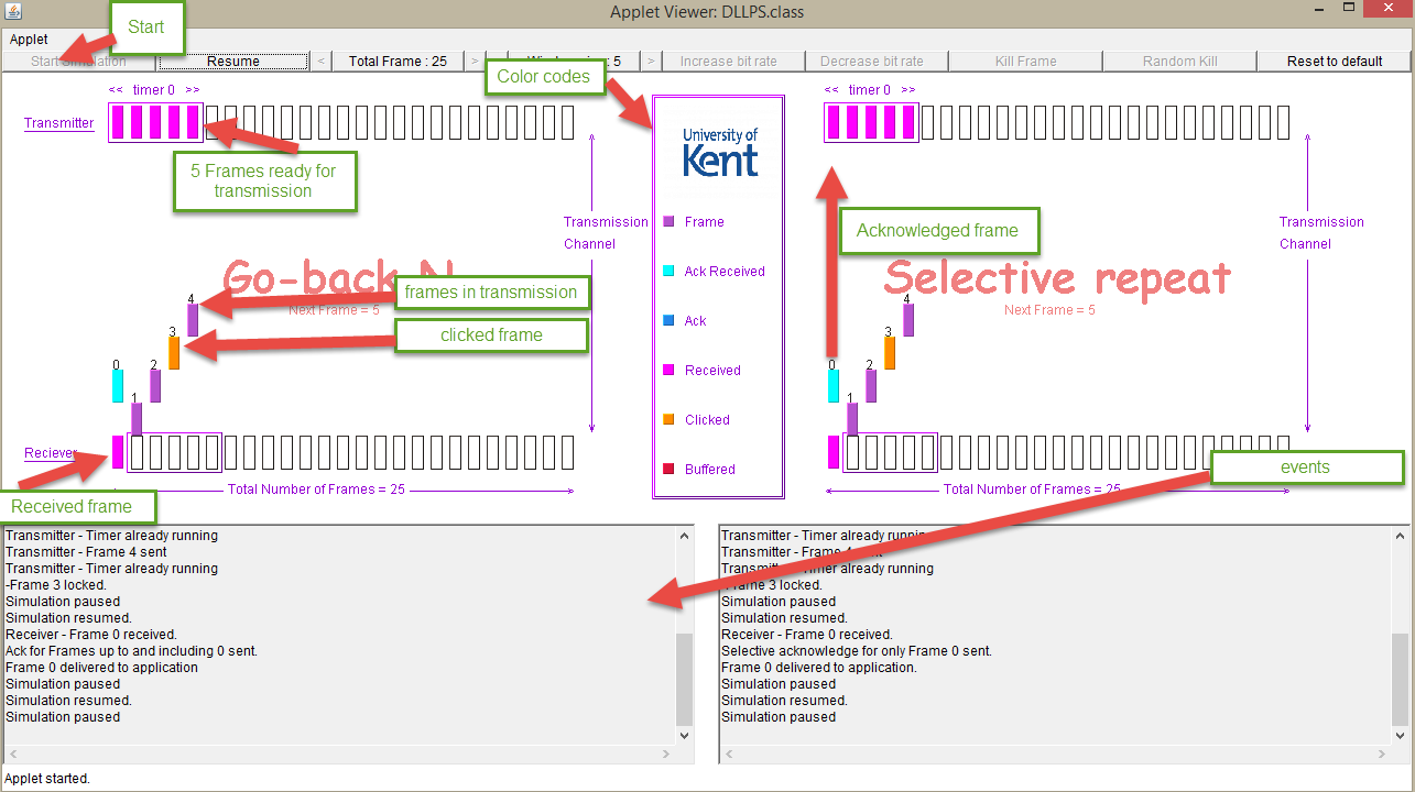
Figure 3: Other buttons and a clicked frame
As a continuation from figure 2a, in figure 2b the last bit arrives for the frames 0 to 4. The frames are checked if it is in order , if everything is okay, an acknowledgement for each of the frames is generated and sent to the transmitter confirmation that the transmission was successful .Then the next sequence of frames(frames 5-9) to be sent are initiated. All this information is noted in the events window.
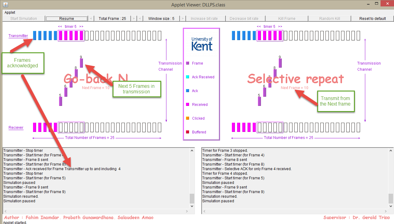
Figure 2a: Simple transmission that occurs when the start button is clicked
There are other calls that are made when other buttons are used such as if a frame is killed or out of order frames or lost acknowledgement. This has been discussed in the next section.
3. Events, States and their functions
During transmission of frames through the transmission channel there are other events or states that can be initiated if the person using the application makes use of certain buttons. These function are called when any of these buttons are clicked or selected.
The following buttons which can be used in the application are explained below. This includes the function they perform when used
.
Start Simulation button
This button starts the simulation with the default settings such as window size and numbers. The transmission of frames begins after a brief wait. Figure 1 shows the start simulation button in action.
Pause button
This triggers the pause state when the frames are in transition to its destination.
Resume
This button allows the simulation to return from the pause state.
Kill frame
Allows the user to kill frame after the frame has been clicked beforehand. The frame 5 in figure 3 which was clicked turns to an orange color for both GBN and SR. The frame continues its transit while can then quickly select the kill frame button otherwise the frame will be transmitted and acknowledged
Random Kill
This button is used to introduce errors to see how the program works under errors.
Reset to default
The simulation application is reset to default settings that is to a state that restores the application for new simulation to be started. In other words the button restores the values of windows size to 5 and number of frames to 25.
Total frames
The default number of frames is set to 25. This can be modified to reduced value or returned to the maximum value which is 25. The minimum number of frames is 1. This number of frames is dependent on the windows. The total frames can be one if and only if the windows size is 1.
Windows Size
The size default value is 5. The Windows length determines the number of frames that can be transmitted through the channel. It can increased or decreased and the minimum is one frame.
Increase bit rate
This is used to increase the number of bits that occupies a frame. It makes the frames to looks small but in reflecting a real network. This occupies more bits transmitting within the propagation time.
Decrease bit rate
This is used for decreasing the number of bits that occupies a frame. It makes the frames to looks longer but in reflection of a real network the frames occupies small number of bits transmitting within the same propagation time .
The buttons are shown in figure 3.
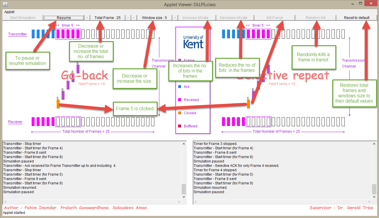
Figure 3: Other buttons and a clicked frame
4. Other events that affect the frames
4.1 Increase bit Rate and decrease bit rate effects
The simulation can take different modes of operation depending on what the user want to achieve. For instance a user may want to transmit a total number of frames equals to 15, the windows size button is clicked to decrease it on the left. The same applies to the window size which is also decreased by clicking on the left to get a value of 8 as the window size. This is all shown in figure 4a below. As seen here when the increase bit rate function is clicked, the frame size decreases but accommodate more bits that is transmitted to the receiver .This changes affect Go Back N and Selective repeat protocols simultaneously.
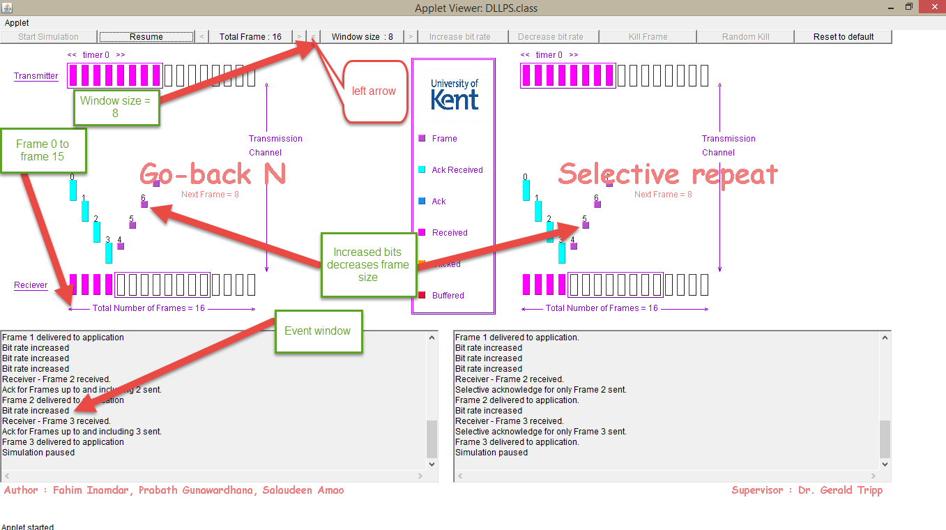
Figure 4a - Increase Bit rate and its effect
Also, as shown in figure 4b if the decrease bit rate function is used the frame sizes become larger. This indicates the number of bits occupying the frames is small. The statement “bit is decreased” is recorded in the event window or text area.
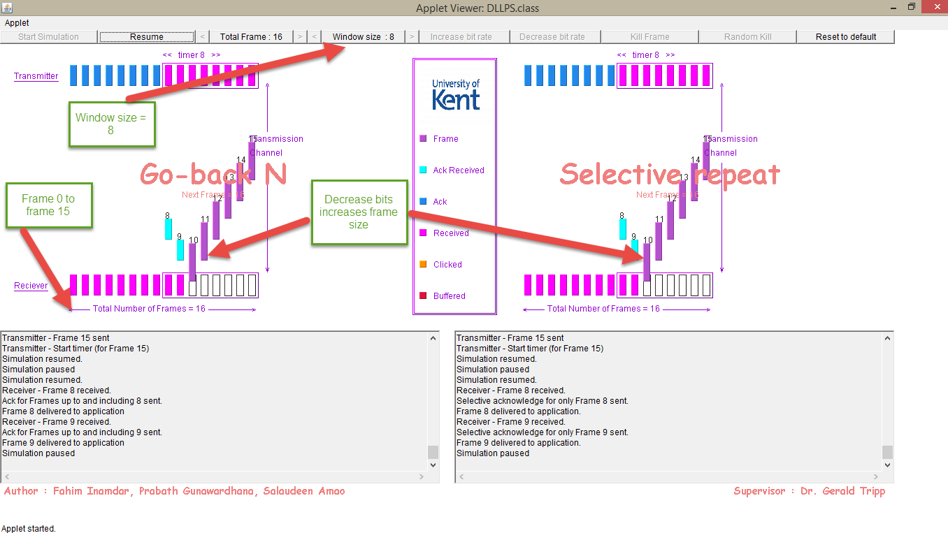
Figure 4b - Decrease Bit rate and its effect
4.2 Lost Frames
A user can either cause errors in transmission by click a frame and using the kill frame button or by using the Random kill button. In figure 5a Frame 5 is lost for both Go Back N and Selective Repeat Protocols. This is recorded in the event window. The protocols works differently to resend this frames.
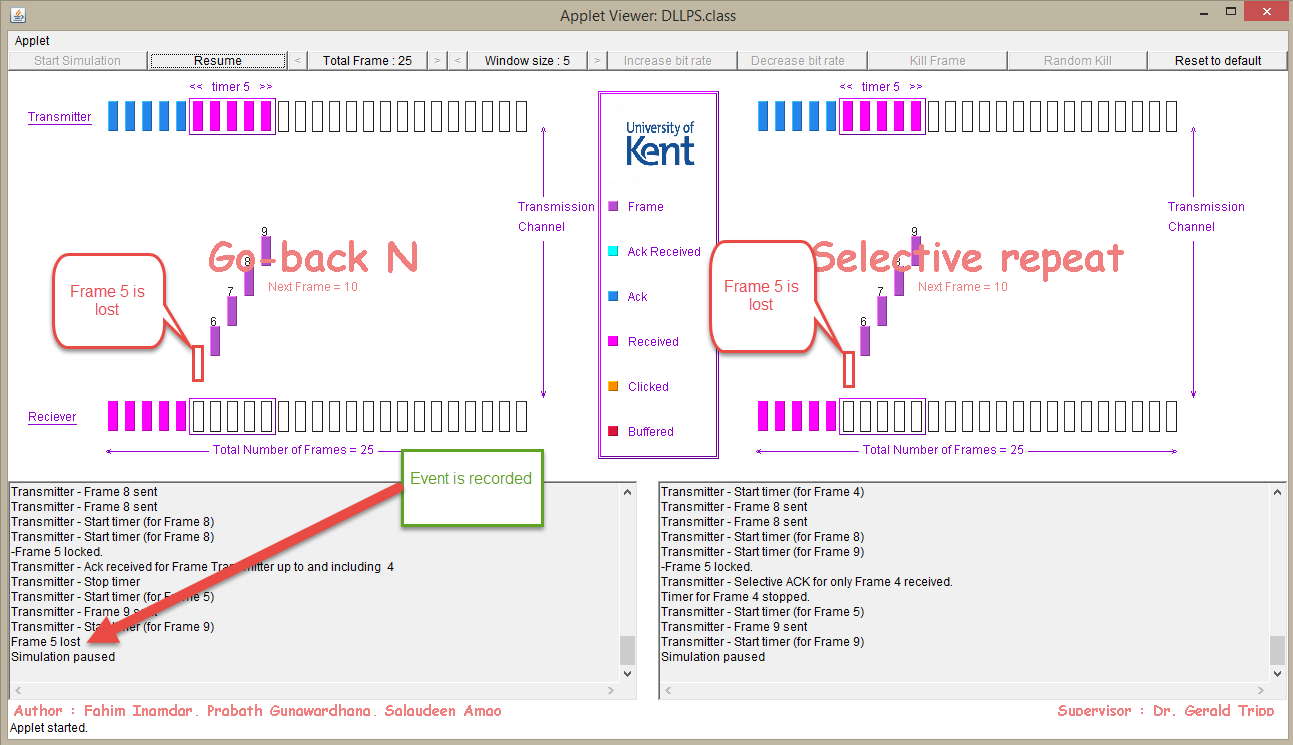
Figure 5a - Frame 5 is lost for both protocols
In the Go Back N ARQ protocol the timer elapses for the frame 5 which is lost to be received by the receiver and so frames 6 to 9 which has been transmitted and acknowledged are dropped .The timer restarts for frame 5 to be transmitted. As demonstrated in figure 5b. Frames 5 to 9 are then retransmitted as timer 5 begins and then acknowledged. However for the Selective repeat protocol the frames 6-9 are buffered and recorded as out of order in the event window. The frame 5 is then selectively retransmitted as the timer 5 begins.
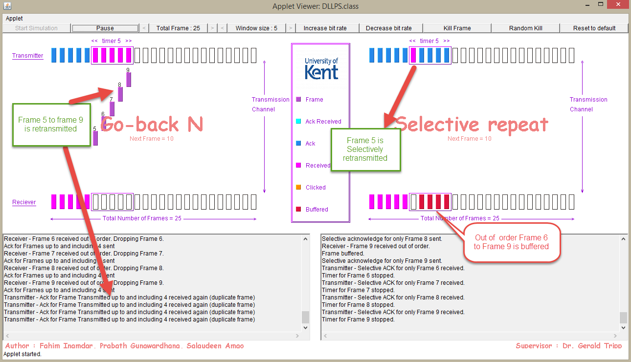
Figure 5b: Lost frame 5 is identified and retransmitted in GBN and SR
A similar example for lost frames
In this example, the window size is 8 and total number of frames is 15, both GBN and SR protocols has frame 6 killed or lost. For the GBN, the protocol “goes back to the lost frame” in this case it is frame 6 and then frame 6 to 13 is retransmitted while in the SR frame 7 to 13 is buffered as the timer 6 begins and also the frame 6 is selectively retransmitted and acknowledged . It is after this that the 7 to 13 is delivered to the application. This is shown in figure 6a.
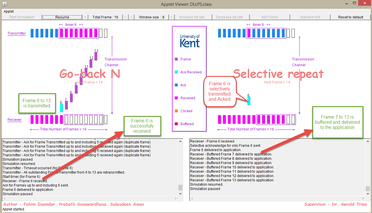
Figure 6a: Different handling of lost frame 6 by GBN and SR protocols
4.3 Total for transmission
The total time for the transmission of the frames is recorded and noted in both event windows. As it can be seen in figure 6b it takes more time for the complete simulation to take place (Transmission time for 15 frames is) in GBN than in SR (Transmission time for 15 frames is.). This will always occur for the simulation whenever a frame is lost.
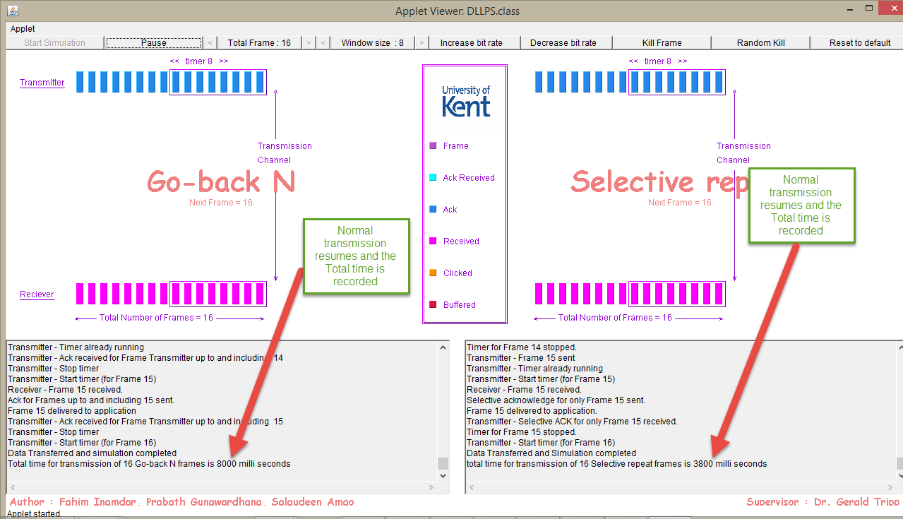
Figure 6b: Total Transmission time for the GBN and SR is recorded